Download the plans HERE courtesy of the UNCC Engineering Department
For the first project in our sophomore design class we built a small air engine. We didn't actually design the engines, but built them to get us acquainted with the machines, what is possible to machine, what isn't etc. It was quite fun and we got a neat little paperweight out of it.
The air engine runs off of you guessed it: compressed air (or steam). This engine is called an oscillating engine. If you are wondering how such an engine operates, there is a great animation at the following link. The only difference between this engine and the animation is it only has the transfer holes above the piston.
http://www.animatedengines.com/oscillatingsteam.shtml
Building the engine was pretty simple. I will explain each piece and post plans in case there is anyone out there that would like to build it. In this article I am trying to be thorough and explain everything but I don't want anyone to feel infantilized so I am making the assumption that since you have a mill, lathe etc that you know how to face a part, use an edge finder etc.
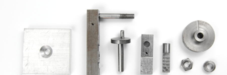
MINIMUM Required Materials
- 4" length of 3/8" square Cold Roll Steel (CRS) Bar
- 1.5" length of Ø3/8" CRS rod
- .19"-32 UNF nut
- 2.8" length of Ø.1875 Drill Rod
- 1.1" length of Ø.25" Drill Rod
- Ø.125 x .38" Dowel Pin (mine was a stock part, it can be purchased)
- 2" length of Ø.63" CRS rod
- 1 5/8" x 1 5/8" piece of .25" thick aluminum plate
- 5/8" length of Ø1" rod
- Small coil spring
- .19"-32 x .5" FHS screw (countersunk)
- .138"-32 x .25" set screw
Required Tools
- Milling Machine (with mill vice, parallels etc)
- Metal Lathe
- Grinder to grind tool bits
- A bandsaw (or at least a hacksaw) to cut your stock
- An arbor press (or hammer) to press the parts together
- A file to remove burrs and clean up cut edges
- Edge Finder
- 3/8" shank endmills 1/8", 3/16", 1/4", 5/16", 3/8"
- 1/2 shank end mills 1/2"
- 3/8" x 3" lathe tool bits
- A parting tool
- Calipers
- 1/4" spotting drill or #2 center drill
- Ø.1240", Ø.1260", .1855", .1885", Ø.2510" reamers
- 10-32, 6-32 taps and dies
- I assume you have a set of drills from 1/16"-1/4" indexed by 1/64"
- #7, #16, #21, #32, #36 drills
Build
Now that you've got your tools and materials its time to start building.
The first step is to cut your materials to the required length:
- 2 1/4" length of 3/8" square CRS for the Body
- 1 3/8" length of 3/8" square CRS for the Cylinder
- 1 3/8" length of Ø.1875 drill rod for the Stud
- 1 1/16" length of Ø.25" drill rod for the Piston
- 1 5/8" x 1 5/8" piece of 1/4" aluminum plate for the Base
- 5/8" length of Ø1" CRS rod for the Flywheel
- 1 1/8" length of Ø.1875" drill rod for the shaft
If you are wondering about the Retainer and Crank, they are parted off of the larger parent piece on the lathe so you will leave the Ø.38" CRS rod and Ø.63" CRS rod alone for now. The nut, pin, spring, screw, and set screw are all stock parts, though if you don't have a pin you will need to cut a .4" piece of .125" drill rod or the like to make one.
Now that all the parts are cut to size it is time to start machining them to the correct size. First all of the features/parts made on the lathe are made, then the rest of the parts/features on the mall are made.
On The Lathe...
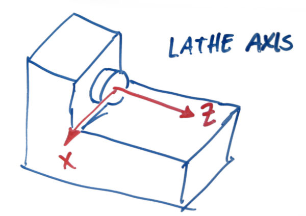
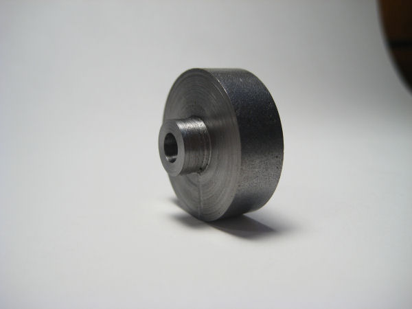
The first piece to be made is the flywheel. Set up your lathe with a 3/8" square tool bit in the tool post. Start by clamping the Ø1.0" piece of CRS in a three jaw chuck. Face the end to get is square then remove the piece from the three jaw chuck and turn it around re-clamp it making sure you have at least .2" overhanging outside the chuck. Measure the length with your calipers to see how much more you have to take off to get it to the correct length then remove it.
The next feature to make is the step where the set screw will go. Make sure that your toolbit has enough rake and clearance to get into a 90 degree corner then cut the feature about 10 thousands undersize then take a finishing pass first in the X direction toward the center of the piece then away from it in the Z direction.
To make the hole through the part first put the drill chuck into the tailstock and insert your spotting drill. Spot the center of the part then change to a #16 drill. I personally like to use cutting oil when drilling so put some cutting oil on the bit and drill the hole through, take care not to pause and let the bit rib as it is cold roll steel and will work harden. If it does harden you will have to punch through the hardened spot you made which isn't particularly good for the bit so avoid it. Once you have the hole drilled through put a Ø.1885" reamer in the chuck, lower your speed to about half of what it was, and using cutting oil ream out the hole. This creates a nice sliding fit hole for the crankshaft to fit in.
That's if for the flywheel, it should looks something like below. Drilling and tapping the hole for the setscrew will be done once all of the lathe parts are done.
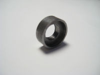
The next part to make on the lathe is the retainer. The retainer is the piece that fits between the spring and the nut.
Take your 1.5" piece of Ø.38" CRS and mount it in the three jaw chuck. Face the end to get it square then mount your drill chuck in the tailstock and spot the center of the piece. Switch to a #7 drill and drill .25" deep.
Now put a Ø5/16" endmill in the drill chuck. It is going to be used to counter bore the hole that was just made. Normally an endmill would never be used in a drill chuck because a drill chuck is designed for axial loads only. But since a simple counter bore will only put axial loads on the the chuck it is acceptable to use the endmill in it. Counter bore to a depth of .06".
That's all for the retainer. Now it just needs to be parted off. Mount a sharp parting tool in the tool post part it off .13" long. As the retainer will be spinning quite rapidly when it comes off a small drill or dowel into the hole in it to catch it so it doesn't fly away and get lost.
Now to make the crank. The crank is the flat disc that holds the crankshaft and the dowel crank pin.
Start by mounting the 2" piece of Ø.63" in the three jaw chuck. Face the end to get it square then mount the drill chuck into the tailstock. Spot the center of the piece then drill a #16 hole .25" deep. Setting the speed to half of what it was and with cutting oil ream the hole you just made to Ø.1855. This diameter will allow the crankshaft to be a press fit into the hole.
Mount a parting tool into the toolpost and part the piece off .15" wide. This is about 17 thousands oversize but because parting tends to give a lousy finish, it allows us to clean up the part later on.
That's it for crank. Later on the mill the hole for the dowel pin will be drilled and reamed. The image below is the crankshaft assembled, though you can see the crank as the middle disc piece.

The piston is up next. There isn't a whole lot to do with it in the lathe, all that needs to be done is face it to length.
Start by mounting the 1 1/16" length of Ø.25 drill rod in a 1/4" collet. Face the end just until it is square, using the file put a small chamfer on the outside edge. Then flip it around and square the other end too. Remove the piece and measure it. Calculate from the drawings how much more needs to be taken off then put re-mount it in the collet and face off however much is necessary.
The picture below is the finished piston. Just so you can see what you are working toward.

At this point facing things to length should be pretty simple so I won't go into depth about it for the next two pieces. Face the 1 1/8" length of Ø.1875" drill rod for the shaft to 1.00" (chamfer both ends with the file after facing). Then take your 1 3/8" length of Ø.1875 drill rod which is going to be the stud and face it to length (1.25"). The stud is threaded so that it can screw into the body and so that the nut to adjust spring tension can be screwed on. With the part still in the collet first thread the .25" long 10-32 thread using the tailstock to keep the die square, then flip the part around and thread the .5" long 10-32 thread the same way.
With those two pieces done your time on the lathe is over and it is time to move to the mill.
Note if you have to make a pin for the crankshaft now is a good time to do that as well.
On to the Mill...
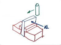
The piece to start with is the base. Since it isn't square it is a little tricky to get it square. I am going to use a couple of illustrations to help me explain how it is done. In the illustrations red is the vice, blue is the part, green is the endmill.
First things first indicate in your mill vice, if you've never done it before just google it, there are lots of instructions out there. As in the illustration below clamp the piece of 1 5/8" x 1 5/8" x 1/4" aluminum plate vertically and face off the top with a 3/8" endmill. Rotate the piece 180 degrees around axis A1 (so that the surface you just milled is against the bed of the mill vice). Once again square up the surface.
Now take the piece and mount it on parallels with the two faces that were just milled parallel are against the clamping surfaces of the vice and one of the two not square edges sticking out of the side of the vice. Using the side of the mill square the edge sticking out. Rotate the part 180 degrees and re-clamp it so the last edge to be squared is sticking out. Square it the same way as the last edge.

At this point the base is nice and square but it is not the correct dimensions. Using your calipers measure the length and width of it. From the plans calculate how much needs to be taken off then clamp it in the mill vice on the parallels. Remove your endmill from the mill and replace it with the edgefinder. Using the edgefinder set the zero at the edge protruding out the side of the vice. Remove the necessary material to get the correct length (or width) then rotate the part 90 degrees and do the same for the second measurement you took.
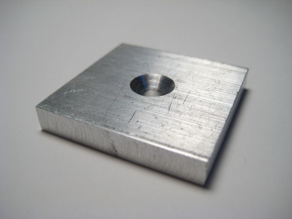
The last thing to do is drill and countersink the hole in the center of the part. Make sure it is clamped with enough hanging out of the vice to edgefind a corner. Replace your 3/16" collet with a drill chuck. Set the zero above one of the corners, then count off to the center of the part (.75" in both directions) drill #7 through then countersink to suit the .19-32 screw that you are using. That's it, the base is done.
The next piece to make is the piston. It needs a flat milled and a hole drilled. First measure the length of it and subtract .813" from it. This is the dimension "X" in the prints. From the measured length also subtract .31" and this will give you the "Y" dimension in the drawings. The reason that these are calculated is the piston will be clamped in a collet block so there won't be any access to the top of the part which is where we are measuring from. So we will be edgefinding from the bottom. Of course if every part was perfect it would okay to measure from the bottom, but since there will be variation in length from one piston to another and the distance from the top of the piston to the hole is critical for the engine to operate we calculate X and Y instead of having them explicitly stated on the prints to ensure accuracy of length.
Clamp the piston in a collet block mounted horizontally in the mill vice making sure that at least whatever your calculated "Y" value is sticking out so you don't hit the collet with the endmill. Using the edgefinder locate the bottom of the piston and the right side. You will also have to zero the height of the mill. The way that I do it is to put the endmill that I will be using in the mill then get a piece of paper I know the thickness of. The paper I use happens to be 4 thousandths thick. Putting the part directly under the endmill with the piece of paper in between them I slowly lower the endmill while moving the piece of paper around underneath it. Right when I feel any resistance in the paper movement I set zero at 4 thousandths lower then I currently am at. This is an easy way that has always worked for me and preserves the finish of your part from scratches. Mill the .075" x "Y" flat using a 1/4" endmill, cutting .025" deep per pass.
Once the flat has been milled move back to the bottom right corner that was set to zero previously. Remove the 1/4" endmill and mount the drill chuck. Move to the center of the part (.125") then move to your calculated "X" dimension. Spot then drill #32 through. Lowering the speed to half and with cutting oil ream the hole to Ø.1260". Clean up any burrs and the piston is done.
Mount the crankshaft in a collet block with the end that will be pressed into the crank disc sticking out. Using the edgefinder locate the end face of the shaft then mount your 3/16" endmill and set the zero to the top of the part. (using the paper method described above). Move to the location specified on the prints and mill the .19" wide flat .03" deep. The purpose of this flat is to give the setscrew a seat. Although it works without the flat, the set screw has a tendency to make a burr on the shaft which makes disassembling the engine a nightmare.
Its time to press the crankshaft into the crank disc, in order to keep everything square. A guide is very handy. Basically a block that is about .75" thick with a .1885 hole drilled and reamed through it then countebored Ø.75" x .18 deep works very well. The crank disc fits in the counterbore which is placed face down on the bed of the arbor press. The shaft is inserted from above (through the .1885 hole) then pressed into the disc. It could be tapped in with a hammer with a lot of care and a block of wood to keep the hammer from damaging the shaft as well.
Mount your newly pressed together crankshaft in a collet in the lathe (I know this is the mill section but this will just take a second...) remember how the crank was parted off too thick? It is time to remove that extra material to give the face a nice finish. Take off whatever is necessary to get the crank disc to tolerance using very light passes (remember it is pressed onto the shaft, not as strong as one homogeneous piece)
Once you have it faced move back to the mill and clamp the crankshaft vertically in the mill vice by clamping the shaft between two v-blocks to make sure it is vertical. Mount the drill press in the mill and with a dial indicator indicate to the center of the crank disc. Move to .188" from the center and spot then drill #32 through. Lower the speed to half then ream the hole Ø.1240" through.
Back at the press the crank pin needs to be pressed in. The easiest way is to make a fixture to keep everything square by drilling and reaming a Ø.1260" hole through a suitably thick piece of scrap. Use this to keep the pin square when pressing/hammering it in. That's it, the crankshaft is done.
The hole in the flywheel still needs to be drilled and tapped. Clamp the flywheel in the vice as shown in the illustration below.
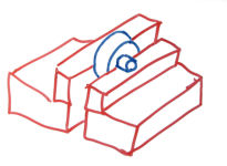
Edgefind off the front face of the large portion of the flywheel (the face you measure .075 from in the prints) and find the center of it. The spotting drill won't be able to fit in close enough to spot this hole so instead mount a #7 drill in the chuck with as little of the drill outside of the chuck as possible (but still able to reach to spot the face). Spot the face then drill #36 through the first wall then mount a 10-32 tap in the drill chuck. Putting the machine in neutral and using the quill feed, lower the tap to the hole you just made and apply a little tension with the quill-feed. Turn the drill chuck by hand so that the tap threads its self into the hole. There isn't a lot of room for the tap to completely cut the threads so you may need to use a bottoming tap or grind the tip of your tap down just a little bit so it can fit. Once the hole is tapped disengage it from the chuck and back the tap out using a tap wrench then your fingers once it is loose enough. That's it, the flywheel is done.
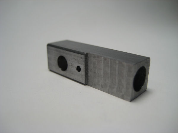
The second to last piece is the cylinder. Start by mounting it horizontally on parallels in the mill vice with one of the ends sticking out. With a 1/4" endmill mill the end square then flip it around and mill the other square while bringing it to the correct length.
Replace the parallels from the previous operation with shorter ones so that when you clamp the cylinder vertically about 1/4" protrudes from the top of the vice. Locate one of the corners and move to the center of the part. Spot then mount a 15/64" drill. Locate the height of the drill using the paper method described above. Drill 15/64" x .72" deep. Lowering the speed to half, with cutting oil ream the hole to Ø.2510"
Clamp the cylinder horizontally on parallels. Using the edge finder find the bottom edge and the center of the part and move .938" to the location of the .1885 through hole. Set your machine zero here. Spot then drill #16 through, then ream it Ø.1885" through. From the newly set zero move down .281" and spot then drill the 1/16" hole through one wall (so that the hole leads to the Ø.2510 hole).
Finally locate the bottom edge again and top surface of the cylinder (again using the paper method) and make the .03" x .56" undercut. That's it, the cylinder is done.
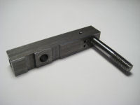
Finally the most fun part of all (e.g. most involved) - the body. First mill it to length using a 1/4" endmill the same way that the cylinder was.
With the part clamped horizontally, with the edgefinder locate the bottom edge and find the center of the part. Move up .625" to where the Ø.1885" hole will be. Spot then drill #16 through. Lower the speed to about half and with oil ream Ø.1885 through.
Move up to the 10-32 hole for the stud. Spot then drill #21 x .34" deep. The hole is drilled deeper than necessary to give the tap enough room. Using the same technique as the flywheel tap the hole 10-32 x .25" deep. Moving down to the location of the two 1/16" holes (1.656" above the base) first move the the right and spot then drill 1/16" through then move to the left and spot then drill 1/16" x .29" deep.
Don't loose your zero at the bottom of the part switch to a collet and mount a 3/16" endmill. Using the paper method described above locate the endmill to the top surface of the part. Mill from right to left the two .19" slots.
Unclamp the part and turn it 90 degrees clockwise so that all of the features you just cut are against the moving jaw of the vice. Re-mount the drill chuck in the mill and locate the bottom of the part using the edgefinder then find the center of the par. Move up to the 1/16" hole (1.656") and spot then drill until it intersects with the other 1/16" x .29" deep hole. You can use the quill feed and drill until you feel resistance drop when it emerges into the other hole, or measure the necessary depth and drill to it.
Unclamp the part and clamp it vertically so that the bottom is facing up. Since the piece is tall and has such a small base you should run a dial indicator up and down the face to see how vertical it is. Small adjustments can be made by loosening the vice slightly and tapping the part with a piece of wood or another soft material. Using the edgefinder locate the center of the bottom then spot and drill #21 x .46" deep. Using the same technique as the flywheel tap the hole .38" deep. All the parts are done, give yourself a pat on the back.


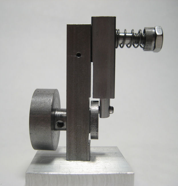
Assembly and Testing
First make sure that all the parts (especially moving ones) are burr free. Assembly is pretty straightforward, put oil on any part that moves when assembling it:
- Screw the stud into the body. If you use pliers make sure you have something soft between them and the stud so you don't scratch it
- Screw the body to the base
- Insert the crankshaft into the body then secure it by screwing the flywheel to the other side (make sure the set screw is against the flat in the shaft)
- Insert the piston into the cylinder then put the cylinder onto the stud, slide it all the way down making sure that the hole on the piston goes on the crankshaft pin.
- Put the spring then the retainer then the nut on the shaft.
You will need to have a source of air to power it. I actually have used a small airbrush compressor and just pressed the hose to the hole in the side.
To run it you will somehow have to attach an air source to the side 1/16" hole that intersects the other 1/16" hole. It might be worthwhile tapping the hole to accept a hose fitting or something. You'll need somewhere around 15psi to start it for the first time usually. Once you get the air source attached give the flywheel a little flick CCW (looking at it from the back) and hopefully it will start. If not check that the air is getting delivered to the cylinder, that the hole in the cylinder lines up with the holes in the body, and that all the parts move freely.
I hope that you enjoyed this article, and if you build this engine please send me a picture and tell me how it went!